How Finite Element Analysis Solved the Bonnevile Dam Crane Mystery
In industries that depend on the flawless operation of large, complex machinery, unexpected failures can lead to significant operational disruptions, financial losses, and safety hazards. Diagnosing the root causes of these failures is often challenging, as traditional inspection methods may not uncover underlying issues in intricate structures where hidden defects can remain unseen.
This is where finite element analysis (FEA) becomes an indispensable tool. FEA enables engineers to simulate and analyze how structures behave under various conditions, providing a detailed understanding of stress concentrations, displacements, and potential failure mechanisms at a granular level. For industrial operators, legal professionals, and insurance specialists, this capability is invaluable when addressing large-scale failures, uncovering hidden defects, or navigating situations where physical evidence is limited or inconclusive.
As a mechanical engineer and naval architect, I've seen my fair share of complex machinery failures. But the case of the Bonneville Dam crane stands out as a prime example of how advanced analytical tools like FEA can crack even the toughest engineering puzzles.
The Challenge: A Cracking Crane in the Columbia Gorge
Picture this: you're at the Bonneville Dam on the Columbia River, about 40 miles east of Portland, Oregon. This dam is a crucial piece of infrastructure, featuring locks that allow barges to navigate inland. Central to its operations is a massive crane used to move cofferdams in and out of the lockway.
But there’s a problem. The crane was developing fractures in its boom welds—serious cracks that raised alarms about the crane's structural integrity and operational safety.
If you know anything about the Columbia Gorge, you'll understand why this was particularly concerning. The area is renowned for its extreme winds, with gusts reaching up to 80 mph. It's a windsurfer's paradise, but for a crane operator? Not so much.
When the Army Corps of Engineers approached me with this problem, I knew we needed more than just a visual inspection. Mapping out the fractures was our first step, but to truly understand why this crane was failing, we needed to dig deeper.
That's where finite element analysis came into play.
What is Finite Element Analysis?
In simple terms, finite element analysis (FEA) is like giving a structure an MRI. This analytical tool allows us to see how forces are distributed throughout a piece of equipment and to pinpoint stress hotspots that might not be visible to the naked eye.
In the case of the Bonneville Dam crane, the analysis followed a meticulous process:
- Field Survey: We conducted a comprehensive field survey to map every crack and fracture on the crane. This step was crucial for validating the FEA model against real-world damage.
- 3D Modeling: A detailed three-dimensional model of the crane's boom was created. This model served as the foundation for the simulation, capturing the geometric intricacies of the structure.
- Data Input: Critical data—including material properties, geometric design specifics, and the loads experienced by the crane (such as wind forces)—were input into the FEA software.
- Simulation: The software divided the 3D model into thousands of finite elements. It then simulated how each element would react under various conditions, particularly focusing on high wind scenarios.
- Analysis: I analyzed the resulting stress maps and displacement diagrams to identify areas where stress levels exceeded the crane's design limits.
The Aha Moment: Wind-Induced Stress Exceeding Design Limits
The FEA results were revealing. Under normal operating conditions, the crane's stress levels remained within safe limits. However, when extreme wind loads were factored in, certain parts of the boom experienced stress far beyond what it was designed to handle.
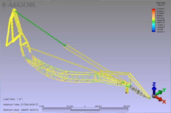
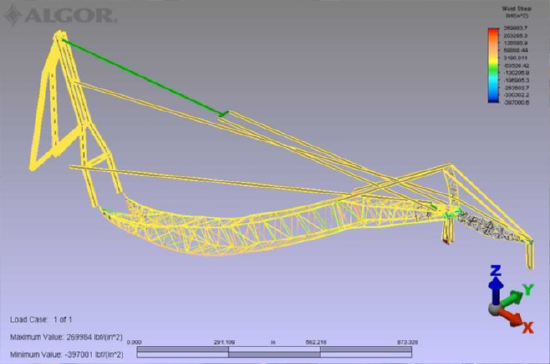
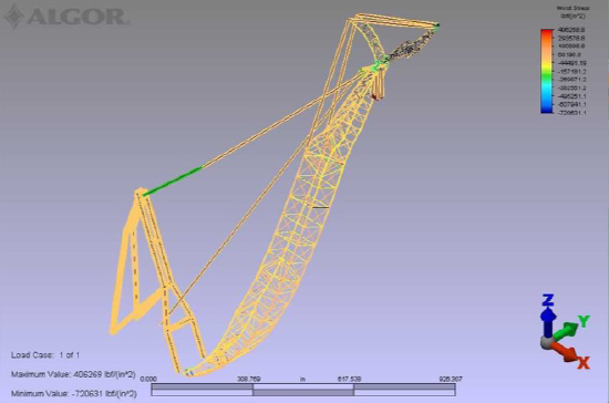
The simulations showed high stress concentrations precisely in the areas where fractures had been observed. This correlation confirmed that the extreme winds of the Columbia Gorge were inducing stresses that exceeded the crane's capacity, leading to the development of cracks in the boom welds.

This series of images showcases three load cases from an FEA, highlighting areas of high stress at various jib and main boom weld locations. Each photo provides a detailed view of critical stress points under different loading conditions.


From FEA to Action
Armed with this knowledge, we were able to provide two key recommendations:
- Operational Limits: We established specific wind speed thresholds for safe crane operation. This immediate action allowed the dam to continue its vital work while mitigating the risk of further damage.
- Structural Reinforcement: Our FEA pinpointed the most vulnerable areas of the boom, particularly in the joints of the 40-foot section. We recommended targeted reinforcements to these areas, providing a long-term solution to prevent future fractures.
The Bigger Picture: FEA Beyond the Bonneville Dam
While the Bonneville Dam crane is a fascinating case study, it's just the tip of the iceberg when it comes to FEA applications. In my work at EDT, I've seen how this tool can revolutionize problem-solving across a wide range of industries:
- In manufacturing, FEA can help identify why parts are failing during production. By simulating the stresses and strains that machinery components experience during operation, manufacturers can redesign parts to enhance durability, reduce downtime, and save millions in potential losses due to equipment failure.
- For the oil and gas industry, we can analyze pipeline integrity or assess offshore platform stability in extreme weather. Simulating dynamic loading conditions, such as ocean currents and temperature fluctuations, allows engineers to predict potential failure points and implement design improvements or preventative maintenance strategies to avert environmental and financial disasters.
- Renewable Energy: FEA is crucial in renewable energy, particularly for optimizing wind turbine blades. These blades experience complex, varying stresses due to wind patterns, and FEA enables engineers to model these forces to improve blade resilience and reduce fatigue. Wave energy systems, a more recent application, similarly benefit from FEA to ensure that structural designs can withstand the punishing marine environment.
- Marine Industry: In marine engineering, FEA provides insights into optimizing vessel structures for strength and efficiency. Modeling stress points on engine mounts or hull sections, for instance, allows us to refine designs for lighter yet robust structures. This capability is essential not only for performance but also for extending operational life under challenging conditions at sea.
The value of FEA lies in its versatility. Whether we're dealing with static loads, dynamic forces, thermal stresses, or even non-linear material behavior, FEA gives us the power to see the unseen and predict the unpredictable.
The Power of FEA in Solving Complex Engineering Challenges
The Bonneville Dam crane case is a perfect example of why I love what I do at EDT, being able to use cutting-edge tools like FEA to uncover the root causes of those problems and prevent them from happening again. As we continue to push the boundaries of what's possible in engineering, tools like FEA will become increasingly crucial. They allow us to design safer, more efficient structures and machinery, and to tackle engineering challenges that would have been insurmountable just a few decades ago.
About the Author
Steven M. Lindholm P.E., P.M.P., NAMS-CMS, is a Consulting Engineer and Assistant Vice President at Engineering Design & Testing Corp. With over 40 years of experience in mechanical and marine engineering, Steve specializes in finite element analysis, failure investigations, and structural assessments.

