A Place for Everything and Everything in Its Place
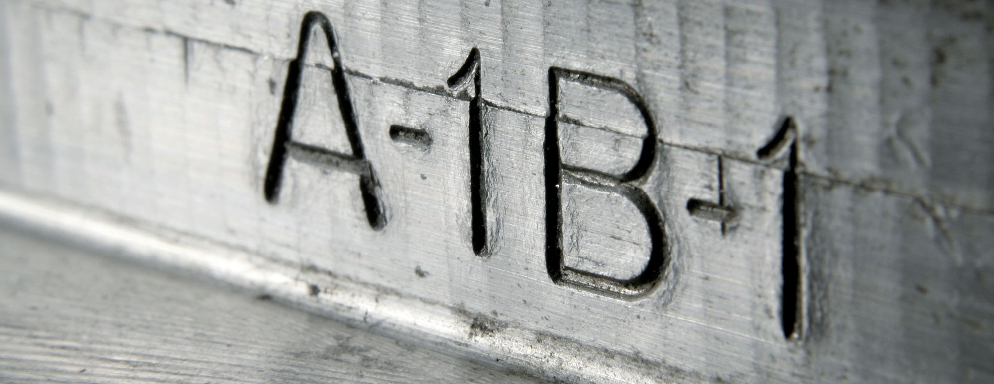
Today’s steel structures are often complex assemblies of components, such as beams and columns. Each beam and column have a unique place in the structural system, which makes the structure function. To ensure that each piece is erected where it belongs, every beam and column is labeled in the fabrication shop with a unique piece mark. Often, this piece mark is a string of numbers and letters as shown in Figure 1.

.
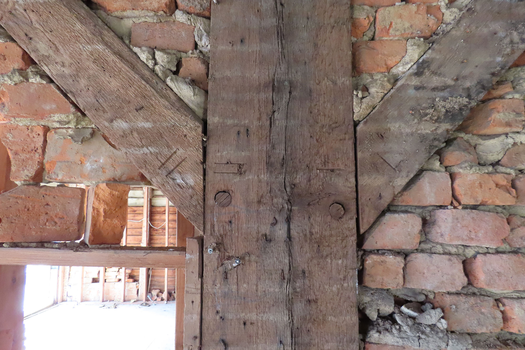
I recently had the opportunity to visit a century-old timber building made in the traditional post and beam style. By today’s standards, such buildings are not considered complex. However, to the craftsmen of the day, each component of the structure usually had a distinctive place in the building. Take for example, a diagonal brace between a post and beam. The diagonal brace requires connections at either end to ensure it engages with the post and beam. The techniques of the day included mortise and tenon connections, which required precise craftsmanship. Given the natural irregularities of timber, every brace wasn’t interchangeable. Each tenon was cut to fit a matching mortise. To ensure each brace was placed in its intended location, match marks were often used. I was pleased to see a set of match marks on a brace-to-post connection during my visit to the century-old timber building. You can see the rudimentary single-tick and double-tick match marks on either side of the post in Figure 2.

The piece mark and match mark both came to mind when I investigated a solar farm a few years ago. The solar farm included acres of photovoltaic arrays mounted on cold-formed steel support structures. The support structures included a series of beams that were attached to cantilevered frames. The frames included four members that resembled two vertical triangles, when assembled. A single vertical post of each frame had been driven into the ground, as shown in Figure 3.

Following a significant snowfall, owners of the newly constructed solar farm noticed distortions among the steel support structures. There was immediate concern that the weight of the snow on the photovoltaic panels resulted in the distortions. We examined the steel support structures and observed a twist in the members that formed the tops of the aforementioned triangles in the cantilevered frames.
We requested design drawings of the steel support structures. The drawings depicted braces between the vertical post and the top member of each frame. The braces connected, at one end, to plates attached to the vertical posts. At the other end, the braces connected to the backs of the top member. Upon review of the drawings, we discovered that the brace-to-post connections were intended to align on the right sides of the connection plates. However, each and every brace of the cantilevered frames had been assembled on the left sides of the connection plates.
After further investigation, including weather data, local snowfall measurements, and design documents, we concluded that the misalignment of the braces resulted in the twist of the top member, not the snow.
While piece marks and, perhaps match marks, would not have prevented this problem, it is worth lamenting how engineered systems often have a place for everything; and the systems often need to have everything in its place in order to work as intended.
About the Author
Edward M. Deegan, Jr., M.S., P.E. is EDT's Mid-Atlantic District Engineering Manager and a Consulting Engineer in our Mid-Atlantic Office. Mr. Deegan provides specialized consultations in the areas of structures and the built environment, including cause of damage, scope of damage, and value of loss. You may contact him for your forensic engineering needs at emdeegan@edtengineers.com or (856) 662-0070.
Learn about how EDT Forensic Engineering & Consulting approaches damage assessment to commercial and industrial incidents and forensic engineering by assigning a file today.

